Shop

JJP Soft Flipper Fix Kit (SFFK)
Price range: $60.00 through $120.00
Tired of the weak flippers in your Jersey Jack pinball machine? Introducing FlipMods JJP Soft Flipper Fix Kit! Installation service available!
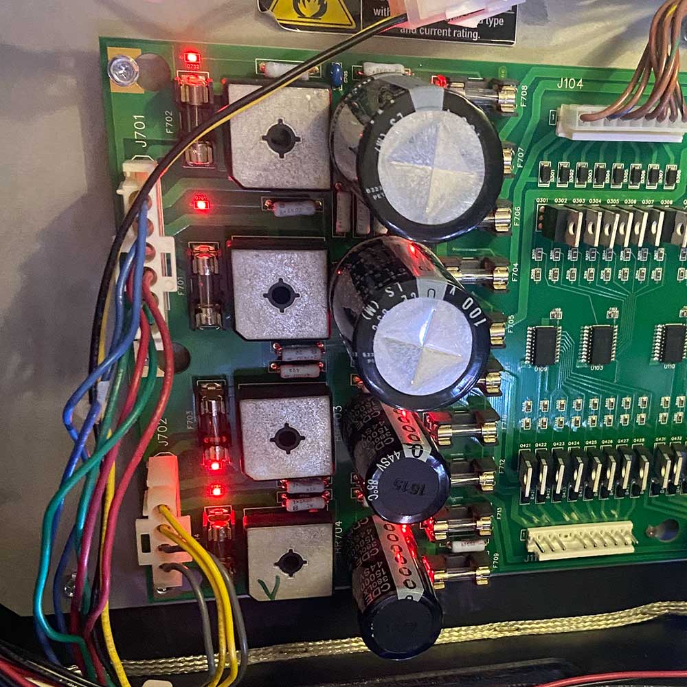
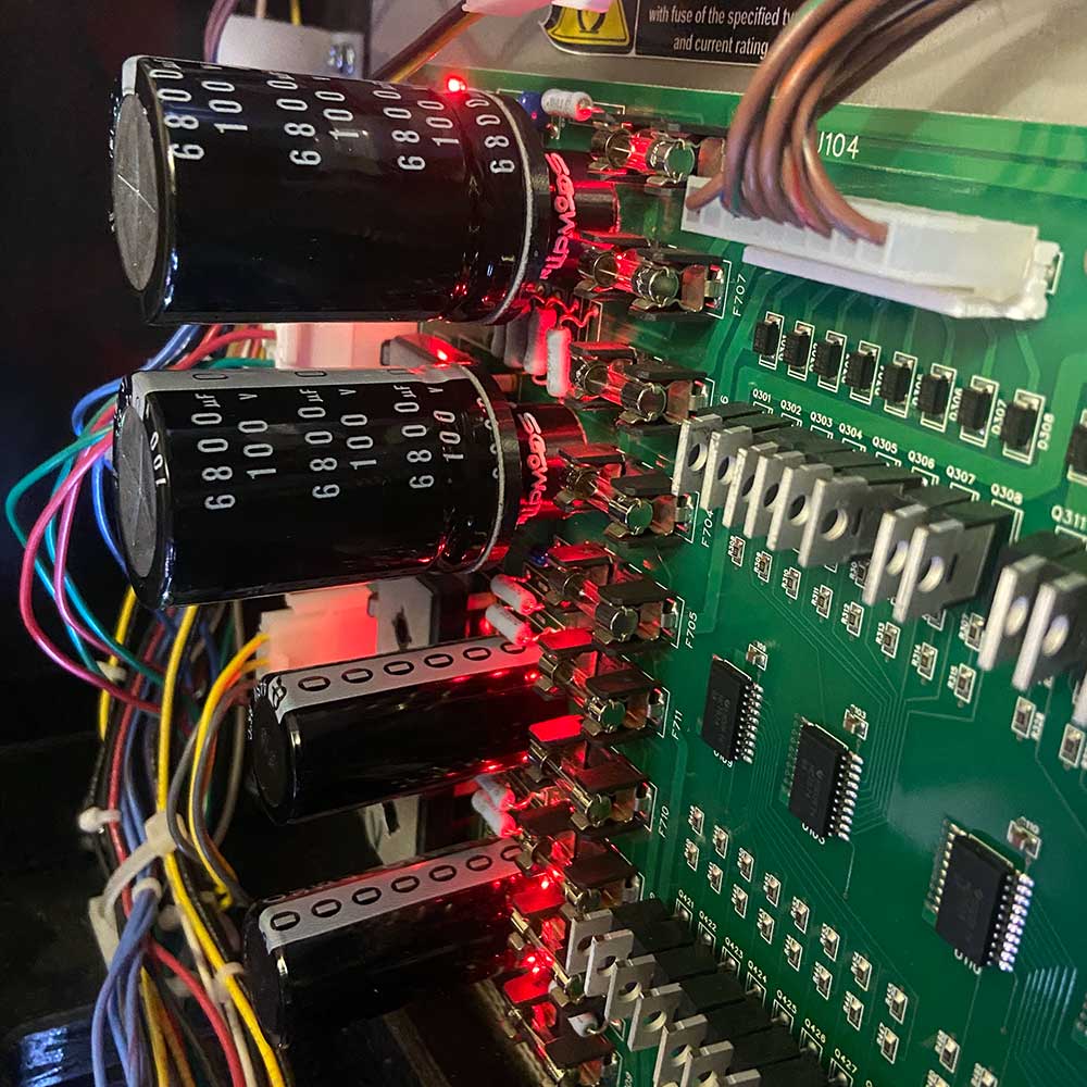
JJP recently released an updated IO Driver board that has been used in recent games including Toy Story 4, The Godfather, and Elton John. This board is almost identical to the existing board, with the exception of the capacitors (C701, and C702) used for the 70V power section which is used for driving the high powered solenoids, as well as the flippers.
It is possible to retrofit existing older IO Driver boards with these new capacitors which provides the same benefit as the newly designed board, at a fraction of the cost.
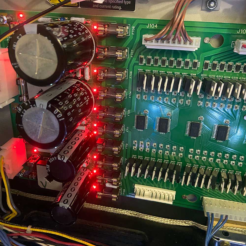
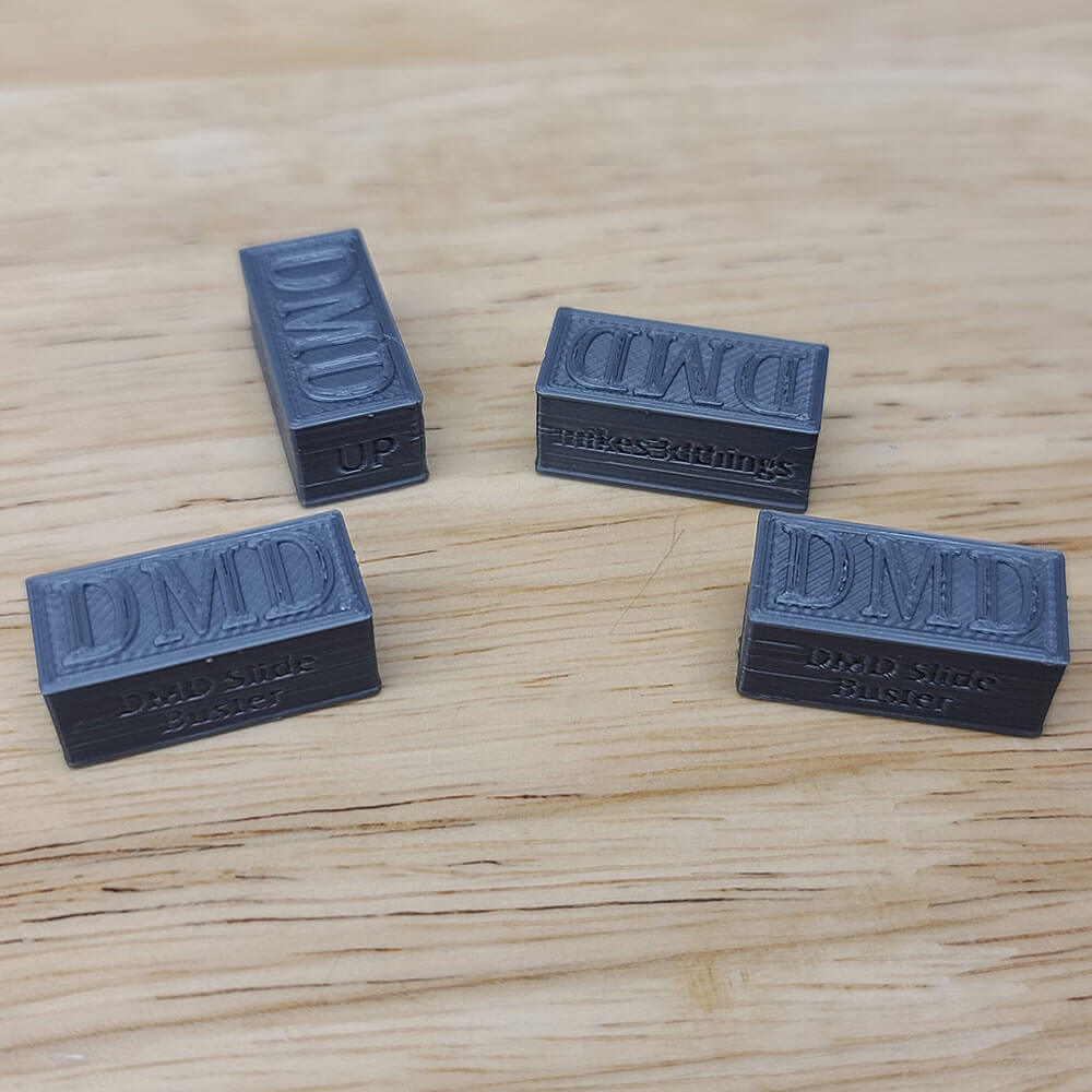
Due to the dimensional differences between the old and new capacitors, the new capacitors are too large to mount directly on the board. A custom engineered standoff was designed to raise the new capacitor above the board. Features of this standoff include:
- The base matches the existing footprint of the older capacitor, ensuring that surrounding components on the board are not damaged, or obscured.
- Provides an air gap between the surrounding bridge rectifiers and the capacitors. This prevents the heat generated by the bridge rectifiers from conducting to the capacitors.
- Provides accessibility to the surrounding fuses.
- Polarity labeling (+ and -) to easily identify proper orientation while installing the assembly.
- The top matches the diameter of the new capacitors to maximize surface area for maximum adhesion between the capacitor and the standoff.
Click the tabs below for additional information.
By using this modification, you acknowledge and agree that you are solely responsible for any consequences, including any damage or issues that may occur.
Kit Details
Kit Details
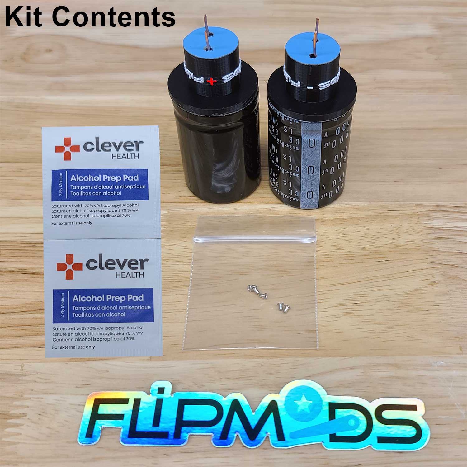
This Kit contains everything needed to replace the 2 3300uF capacitors with larger 6800uF versions including
- 2 Complete capacitor assemblies
- Includes
- High quality capacitors sourced from domestic suppliers.
- Custom engineered stand offs to accommodate the larger capacitors.
- 18 AWG solid Copper wire leads which are pre-soldered to the capacitors.
- Bottom copper leads which can be directly soldered into the board.
- Pre-installed adhesive between the capacitor and the standoff
- Adhesive backing to permanently mount the standoff to the board which reduces vibration forces on the capacitor.
- Includes
- 4 eyelets used for ensuring a good board connection for the new capacitors
- The capacitors (original and new) contain snap leads which can easily damage the through hole plating if they are not removed / installed correctly. If you are experienced at working with this type of capacitor, you may not need to install the eyelets.
- The positive side of the capacitors have traces that pass through the hole, so those holes are the ones most susceptible to damage. The negative side does not use the through hole to connect the traces, but it is still recommended to install these eyelets for a more consistent install.
- Alcohol swabs for preparing the top surface of the board to promote the best possible adhesion for the capacitor assembly
Installation Instructions
Installation Instructions
- Remove the existing capacitors at the top left of the board (C701, and C702)
- The Hakko solder remover is a good tool for this.
- After removing the solder, gently straighten the leads, heat one lead, and gently push the capacitor while applying heat. Repeat with the other lead, gently pushing the capacitor the other direction. Repeat this rocking process to fully remove the capacitors.
- Solder the eyelets from the top of the board (if desired. See Kit Details tab above for more information about this).
- Apply Flux remover to the holes on the top of the board and then clean with the alcohol swab.
- Remove the adhesive cover on the base of the capacitor assembly.
- Observe the proper orientation of the capacitor. Use the polarity indicators on the capacitor and on the standoff to ensure proper orientation. (Orientation should match the other 2 capacitors below C701, and C702
- Insert capacitors, and press down to ensure good adhesion between the board and the base of the standoff.
- Flip board over and solder the leads for both capacitors
- Trim leads
- Apply Flux remover, and then clean using the second alcohol swab.
Installation Service
Installation Service
We are offering the kit + installation service for only $119.99 + return shipping to you, which you will pay for during checkout. After you purchase the kit and service, you will be contacted with further instructions on where to ship the board. Once we receive the board, we will immediately start working on it for minimal downtime. After we are done with the installation, we will send the board back and you will be all set!
Disclaimer: We cannot be responsible for any damage or issues that may occur as a result of this modification.
FAQ
FAQ
Click here to view our FAQ regarding our JJP Soft Flipper Kit Fix.
Reviews (3)
You must be logged in to post a review.
3 reviews for JJP Soft Flipper Fix Kit (SFFK)